| Uploader: | Nikus |
| Date Added: | 10 July 2017 |
| File Size: | 15.50 Mb |
| Operating Systems: | Windows NT/2000/XP/2003/2003/7/8/10 MacOS 10/X |
| Downloads: | 38655 |
| Price: | Free* [*Free Regsitration Required] |
7-segment display basics
A fixed decimal point by wiring one of the DP pins to Vss. These charges are decodef billed to you directly from UPS. Already have an account?
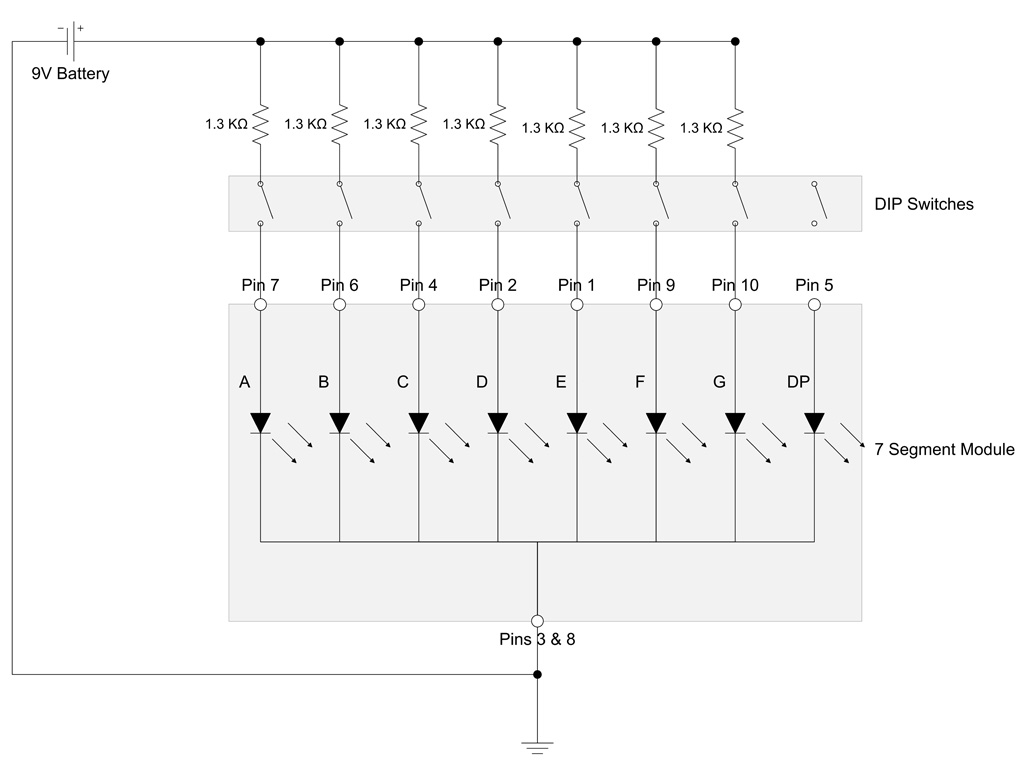
First we need to familiarize ourselves with the 7 segment module. In this circuit, we will build a BCD to 7 segment display decoder circuit using the chip. Seven-segment displays are widely used in digital clocks, electronic meters and other electronic devices that display numerical information.
Those are symbol for LED, to represent the 7-segment display, not normal diodes.
This, for -7segment, would allow the micro to handle other tasks without having to update the display until required. The pin-out for the is shown below, and the datasheet is available at here. We do not have a paywall as our mission is to provide everyone a quality foundational electronics education. The standard segment identification is shown in Figure 1 and segments are named A to G starting at the top and going clockwise with G being the centre segment.
BCD code for both type of display common-cathode and common-anode given in ti table below: The chip is capable of handling up to 20V.
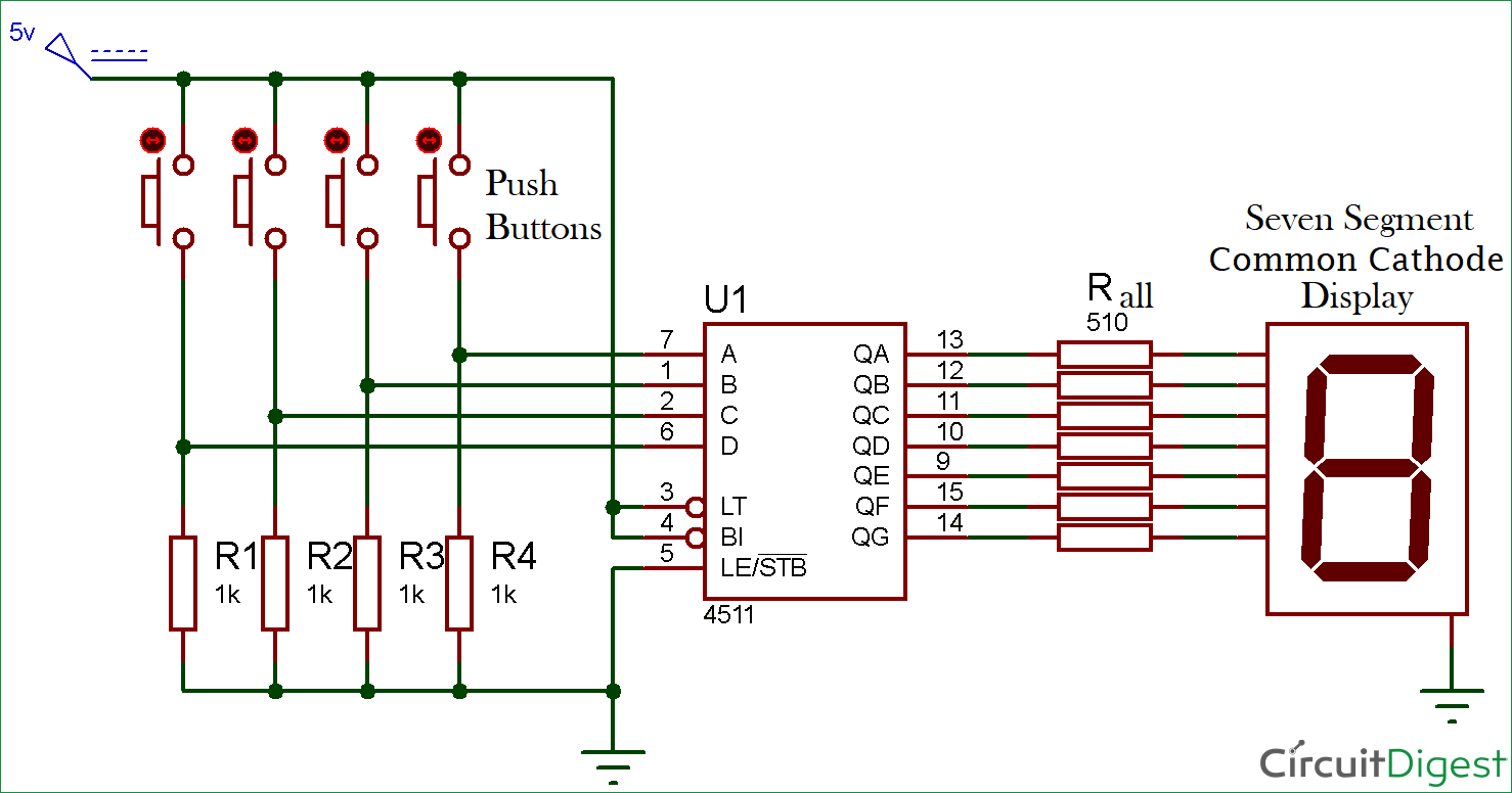
BCD to 7 Segment Converter (4511B)
Depending on the combination of pushbuttons being pressed determines the decimal digit that will be shown on the 7 segment LED display; this is summarized in the table above. However, if you do want to use this feature, you can simply connect it to a pull-up resistor with a pushbutton.
Supplied in a 16 pin DIL package. We are factory specialized in making LED 7-segment display, dot-matrix display, light bar display and abnormity digital display.

Using the pushbuttons, you can manually see how depending on which 7-sfgment we press, how the output changes in response. The can source or sink current for the displays.
Flicker-free 7-segment display Figure 6. This pin would blank all the outputs if connected LOW or to ground. Every LED has a maximum forward current and forward voltage.
This connection is available on pins 3 and 8. Hacking the power buses The power Using binary coded decimal BCD7-segmnet can display any numerical digit on the 7 segment display from 0 to 9- using only 4 pins.
When HIGH, it is store mode. Otherwise, without this chip, to display all the decimal digitsyou would have to use 7 pins; so it saves us 3 pins. Leave a reply Click here to cancel the reply Your email address will not be published.
7-segment display basics | LEDnique
Note that the display decimal points are not controlled by the Being that we don't wish to use this feature, we simply connect it permanently HIGH. So, for example, if 7segment want to show the decimal number 5, we give a value of to the DCBA data pins. Max quiescent current consumption: Once you do this the number will be updated on the 2 LED modules.
Pull high to latch the outputs. This leaves the designer with several options:. Posted by Michael Lockhart on Tuesday, 2 October As might be expected, package pin-count is reduced by using a common pin for one side of all the LEDs.

No comments:
Post a Comment